
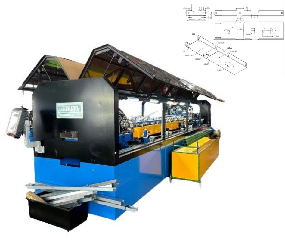
Description of Bridging / Carrying Channel Roll Forming Machine
ZTFRM bridging channels are utilized for reinforcing both non-loadbearing and loadbearing steel stud walls and partitions. These channels lock into place within the stud knockout, enhancing resistance against twisting caused by wind or axial loads. Additionally, bridging channels are the preferred method for installing drywall ceilings, where furring channels are connected perpendicularly and suspended from the structure above.
Channel
1 ½”×½” Channel×12ft
Bridging channels, commonly attached to steel studs using clips or welds, serve as an effective method for resisting stud rotation and minor axis bending due to wind and axial loads. The bridging channel is inserted through the stud knock-out and secured using bridging clips and screws. Typically, lateral bracing is installed at a maximum spacing of 48 inches on center.
- Corrosion Protection: Features a galvanized coating.
- Installation:Designed for easy application.
- Versatility: Suitable for both welded and screw fastening methods.
- Bracing Requirement: To ensure proper bracing of steel stud framing, bridging clips must be used in conjunction with screws. Inadequate attachment of the bridging channel to the steel framing member will result in insufficient bracing.
- Compatibility: Designed for use with 3-5/8”, 6”, and 8” steel studs.
Bridging/Carrying Channel Machine(3/4”×1/2” Channel×12ft) Specification ll
A 3/4”×1/2” channel, measuring 12 feet in length, is frequently used as a bridging channel, commonly attached to steel studs using either clips or welds. This method helps to prevent stud rotation and minimizes axis bending due to wind and axial loads. The bridging channel is threaded through the knockout holes in the studs and secured with bridging clips and screws. Typically, lateral bracing is installed with spacing not exceeding 48 inches on center.
Featuring a galvanized coating for corrosion resistance, this channel allows for quick and straightforward installation. It is suitable for both welding and screw applications. To ensure proper bracing of steel stud framing, bridging clips should always be attached with screws, as the channel alone does not provide adequate bracing unless properly fixed to the steel frame. It is designed for use with steel studs measuring 1-5/8” and 2-1/2″ in size.
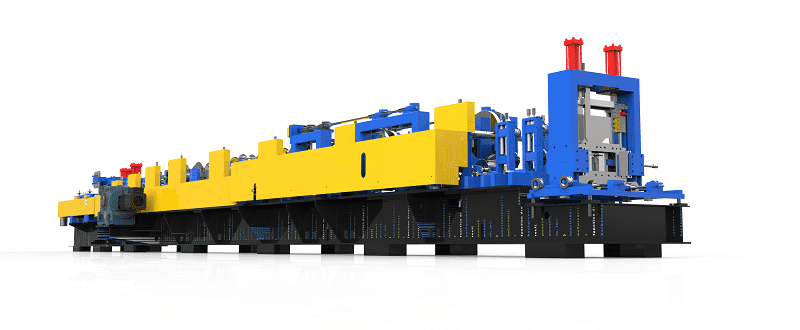
Profile Drawing:


Bridging / Carrying Channel Roll Forming Machine working flow:

The Technical Specifications Of The Bridging / Carrying Channel Roll Forming Machine:
Bridging / Carrying Channel rolling forming machine |
||
| 1.Formed Material | GI | Thickness: 0.4-0.6 mm |
| 2.Decoiler | Hydraulic automatic decoiler | Manual decoiler(will give you as free) |
| 3.Main body | Roller station | 12rows(As your requirement) |
| Diameter of shaft | 45mm solid shaft | |
| Material of rollers | 45# steel, hard chrome plated on the surface | |
| Machine body frame | Metal steel welded | |
| Drive | Gearbox transmission | |
| Dimension(L*W*H) | 5500*800*1200(customize) | |
| Weight | About 3T | |
| 4.Cutter | Automatic | cr12mov material, no scratches, no deformation |
| 5.Power | Motor Power | 7.5KW |
| Hydraulic system power | 5.5KW | |
| 6.Voltage | 380V 50Hz 3Phase | As your requirement |
| 7.Control system | Electric Box | Customized(famous brand) |
| Language | English(Support multiple languages) | |
| PLC | Automatic production of the whole machine. Can set batch, length, quantity, etc. | |
| 18.Forming Speed | 0-50 m/min(customized) | Speed is adjustable according to customer’s request |
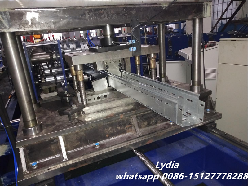
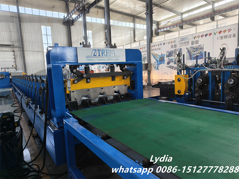
More pictures of the machine:


Light Gauge Steel Framing Machine Specification Width(web): 89mm Height(flange): 41mm Lip:7-12mm The machine match with 3 sets punching die(75~96/138-159/180-200)mm […]
Cable Tray Machine Profile Drawing: CABLE TRAY MACHINE INFO. OF STEEL MATERIAL: Ø Raw material request: […]
2” Composite Metal Decking Roll Forming Machine Profile: 2″ Composite Profile size: 2″ Forming Speed: […]
Specializations Steel framing machines for wall panels, trusses, and floor joists in residential and commercial […]
STAY IN THE LOOP

